Category: United Kingdom (page 1 of 1)

texecom premier elite engineer manual

The Texecom Premier Elite Engineer Manual serves as a comprehensive guide for installing, configuring, and maintaining the Premier Elite series of security systems. Designed for engineers, it provides detailed insights into system architecture, troubleshooting, and advanced features, ensuring optimal performance and security. Key topics include zone configuration, integration with GSM modules, and routine maintenance procedures.

1.1 Overview of the Premier Elite Series

The Texecom Premier Elite Series is a high-performance security system designed for reliability and scalability. It offers advanced features like expandable zones, multiple user codes, and event logging. The series includes panels such as the Premier Elite 24, which supports up to 24 zones and 25 user codes, making it suitable for both residential and commercial applications. Its modular design allows integration with keypads, zone expanders, and communication modules, ensuring flexibility and adaptability to varying security needs. The system also includes emergency alarm functionality and is backed by comprehensive documentation, making it a robust choice for modern security requirements.

1.2 Importance of the Engineer Manual for System Configuration

The Texecom Premier Elite Engineer Manual is crucial for configuring and optimizing the security system. It provides detailed step-by-step instructions for installation, zone setup, and user code management. Engineers rely on it for troubleshooting common issues and understanding system architecture. The manual also covers integration with devices like keypads and GSM modules, enhancing functionality. It ensures proper setup to avoid configuration errors and potential security vulnerabilities. By following the manual, engineers can expand the system as needed and perform routine maintenance effectively. This guide is essential for maintaining system reliability and ensuring all components work seamlessly together to provide robust security solutions.

System Architecture and Components

The Premier Elite system features a modular architecture with a central control panel, expandable zones, and peripheral devices like keypads and zone expanders for enhanced functionality.

2.1 Key Components of the Premier Elite Panel

The Premier Elite panel includes a central processing unit, keypad interfaces, and expandable zones. It supports up to 24 zones, with options for Double Pole or End Of Line configurations. Key features encompass user codes, event logging, and integration modules for GSM communication. The system is designed for scalability, allowing engineers to add peripherals like zone expanders and keypads. Its robust architecture ensures reliable operation, with features tailored for both residential and commercial security needs. Engineers can customize settings to meet specific requirements, ensuring a tailored security solution.

2.2 Expandability and Zone Configuration

The Premier Elite panel offers exceptional expandability, starting with 8 zones and scalable up to 24 zones using expanders. Engineers can configure zones as Double Pole or End Of Line, with options for customizing zone types and EOL modules. The system supports multiple keypads and areas, allowing tailored security solutions. Zone configuration is straightforward, enabling engineers to define zone properties, such as alarm types and sensitivity settings. This flexibility ensures the system adapts to various security needs, from small residential setups to larger commercial environments. Expandability is further enhanced by compatibility with peripheral devices, ensuring a robust and scalable security framework.

Installation and Setup

The Premier Elite system requires careful hardware installation, followed by zone and peripheral device connections. The process ensures seamless integration and optimal system performance from the start.

3.1 Hardware Installation Steps

Begin by mounting the Premier Elite panel securely, ensuring access to all connectors. Connect the power supply, carefully observing polarity to avoid damage. Install zones by wiring detectors and keypads, configuring end-of-line resistors as needed; Peripheral devices, such as motion sensors and sirens, are connected next, following the system’s wiring diagram. Keypads and zone expanders are installed to enhance functionality and expandability. Communication modules, like GSM, are integrated for remote monitoring. Finally, perform initial testing to verify all components function correctly. Always follow safety guidelines and manufacturer instructions for a reliable setup. Proper installation ensures optimal system performance and security.

3.2 Connecting Zones and Peripheral Devices

Connect zones to the Premier Elite panel by wiring detectors and keypads, ensuring correct polarity and termination. Use end-of-line resistors for normally closed zones and tamper switches for added security. Peripheral devices, such as motion sensors and sirens, are connected to designated terminals, following the system’s wiring diagram. Keypads and zone expanders are linked to the main panel to enhance functionality. Ensure all connections are secure and properly insulated to prevent interference. Test each zone and device to confirm correct operation. Use the Premier Elite ComGSM module for remote communication. Follow the manual’s guidelines for wiring and configuration to ensure reliable system performance and security. Proper connectivity is vital for optimal functionality.

Configuration and Programming

The Texecom Premier Elite Engineer Manual provides detailed guidance on configuring and programming the system, ensuring secure and efficient setup of user codes, access levels, and peripheral devices.

4.1 Setting Up User Codes and Access Levels

Setting up user codes and access levels is crucial for system security. The Premier Elite series supports up to 25 user codes, each with customizable access rights. Engineers can assign codes to users based on their roles, ensuring restricted access to sensitive areas or functions. The system allows for multiple access levels, enabling hierarchical control over user permissions. This feature ensures that only authorized personnel can perform specific actions, such as arming/disarming the system or viewing event logs. The manual provides step-by-step guidance on programming these codes and levels, ensuring a secure and efficient setup. Proper configuration is essential to prevent unauthorized access and maintain system integrity.

4.2 Configuring Keypads and Zone Expanders

Configuring keypads and zone expanders is essential for enhancing system functionality. Keypads provide user-friendly interaction with the Premier Elite panel, while zone expanders allow for increased connectivity. Engineers can program keypads to display custom messages and control specific zones or areas. Zone expanders enable the system to accommodate up to 24 zones, offering scalability for larger installations. The manual outlines steps for addressing and configuring these devices, ensuring seamless integration with the central control panel. Proper setup of keypads and expanders ensures reliable performance and flexibility, catering to diverse security requirements. This configuration process is critical for optimizing system responsiveness and user experience.

Advanced Features and Integration

The Premier Elite system supports advanced integration with GSM and communication modules, enabling remote monitoring and control. It also offers seamless compatibility with third-party security systems, enhancing functionality.

5.1 Integration with GSM and Com Modules

The Premier Elite series seamlessly integrates with GSM and communication modules, allowing for remote system control and monitoring. Engineers can configure these modules to send event notifications via SMS or email, ensuring timely alerts for system activities. Additionally, the GSM module enhances connectivity in areas with unreliable landline services, providing a reliable communication pathway for alarm signals. This integration ensures that users receive critical updates, even when they are not physically present at the system. The manual provides detailed steps for setting up and testing these modules, ensuring a secure and efficient communication setup.

5.2 Setting Up Event Logs and Reporting

The Texecom Premier Elite system offers robust event logging and reporting capabilities, enabling engineers to monitor and analyze system activities effectively. The event log can store up to 500 events, providing a detailed history of system interactions, such as arming, disarming, and alarm triggers. Engineers can configure report settings to generate summaries of system activities, which are useful for maintenance and troubleshooting. The manual guides on how to access and interpret these logs, as well as how to customize report formats for specific needs; This feature ensures transparency and accountability, making it easier to identify patterns or issues within the security setup. Regular review of event logs is essential for maintaining system integrity and performance.

Troubleshooting and Maintenance

This section provides diagnostic techniques and maintenance tips to ensure optimal system performance and reliability, covering common issues and routine checks for system longevity and stability.

6.1 Common Issues and Diagnostic Techniques

Common issues with the Texecom Premier Elite system often relate to zone wiring, communication module connectivity, or power supply faults. Engineers can use diagnostic tools like event logs and system reports to identify problems quickly. For zone-related issues, checking wiring connections and ensuring proper end-of-line resistors are in place is essential. Communication failures with GSM or IP modules may require verifying signal strength or resetting the module. Power issues can be resolved by checking the PSU and ensuring proper voltage. The system’s event log provides detailed insights into historical faults, aiding in root cause analysis. Regular diagnostics help prevent recurring issues and ensure system reliability.

6.2 Routine Maintenance for Optimal Performance

Regular maintenance is crucial for ensuring the Texecom Premier Elite system operates efficiently. Engineers should perform routine checks on battery health, wiring connections, and power supplies to prevent unexpected failures. Updating firmware and software ensures compatibility and enhances security features. Additionally, cleaning keypad surfaces and sensors helps maintain responsiveness and accuracy. It is recommended to test all zones and communication modules periodically to identify potential issues early. Backing up system configurations prevents data loss during upgrades or resets. By following a structured maintenance schedule, engineers can ensure the system remains reliable, secure, and performs at its best over time.

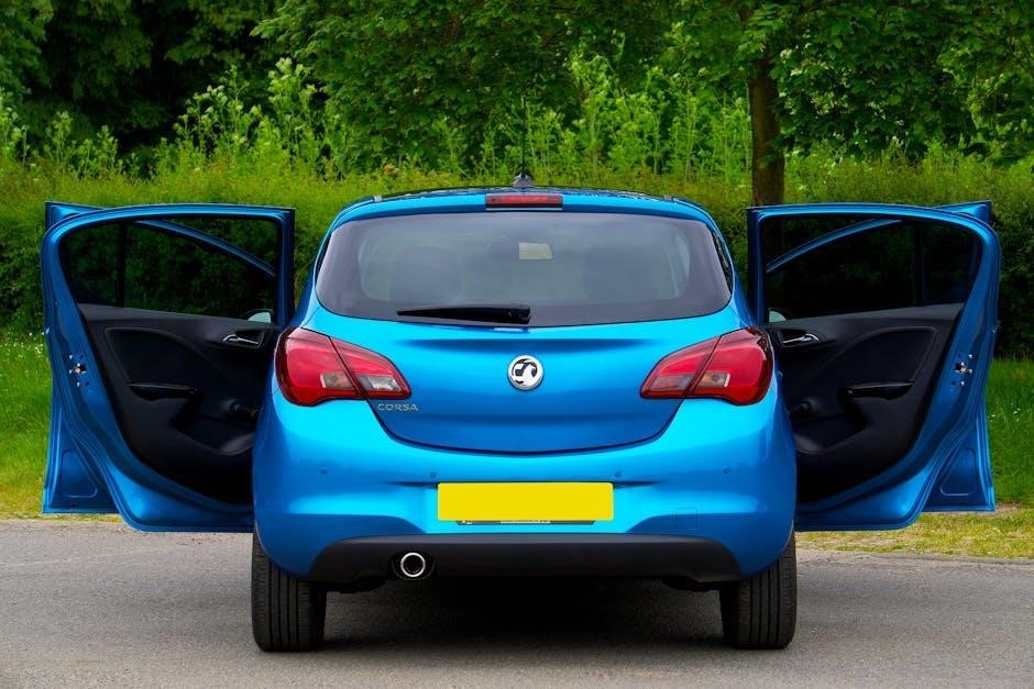
vauxhall corsa d wiring diagram pdf

Welcome to the Vauxhall Corsa D Wiring Diagram guide. This essential resource helps users understand the electrical circuits of their vehicle, aiding in repairs, troubleshooting, and customization.

Overview of the Vauxhall Corsa D Wiring Diagram PDF

The Vauxhall Corsa D Wiring Diagram PDF is a comprehensive guide detailing the electrical systems of the Vauxhall Corsa D. It includes detailed schematics, circuit diagrams, and component locations, essential for troubleshooting and repairs. This resource is invaluable for both DIY enthusiasts and professional mechanics, providing clear and precise information to diagnose and fix electrical issues effectively. The PDF is structured to help users navigate through complex wiring systems with ease. It covers various electrical circuits, ensuring that users can identify and resolve faults efficiently, making it an indispensable tool for maintaining and upgrading the vehicle effectively.

Importance of Understanding the Wiring Diagram

Understanding the Vauxhall Corsa D wiring diagram is crucial for safe and effective electrical system maintenance. It helps identify components, diagnose faults, and perform repairs accurately. By familiarizing yourself with the diagram, you can avoid electrical shocks, short circuits, and costly damages. This knowledge enhances troubleshooting efficiency, reduces guesswork, and ensures compliance with manufacturer standards. Whether you’re a DIY enthusiast or a professional mechanic, understanding the wiring diagram empowers you to address issues confidently, saving time and money while maintaining your vehicle’s performance and longevity.

Key Components of the Vauxhall Corsa D Wiring Diagram

The Vauxhall Corsa D wiring diagram includes detailed electrical system overviews, major circuit diagrams, and a legend explaining symbols. These components provide a clear guide for repairs and diagnostics.

Electrical System Overview

The Vauxhall Corsa D’s electrical system is complex, comprising multiple interconnected circuits. It includes the battery, alternator, and Electronic Control Unit (ECU), which manage power distribution and regulate electrical functions. The system supports essential features like lighting, wipers, and infotainment, while also controlling advanced components such as ABS and engine management. Understanding this overview is crucial for diagnosing faults and performing repairs. The wiring diagram provides a detailed layout of these circuits, helping technicians and enthusiasts trace connections and identify issues efficiently. This knowledge is vital for maintaining optimal vehicle performance and safety.

Major Circuit Diagrams

The Vauxhall Corsa D wiring diagram includes detailed layouts of major electrical circuits, such as engine management, lighting systems, and power distribution. These diagrams illustrate how components like the ECU, sensors, and actuators interact. Key circuits include the starting system, charging circuit, and fuel injection control. They also cover essential systems like ABS, airbags, and infotainment. By analyzing these diagrams, users can trace connections, identify potential faults, and perform precise repairs. This level of detail ensures a comprehensive understanding of the vehicle’s electrical architecture, making troubleshooting and customization more accessible and efficient for both professionals and enthusiasts.

Legend and Symbols Explanation

The Vauxhall Corsa D wiring diagram includes a detailed legend that explains the symbols and abbreviations used throughout the document. This section is crucial for interpreting the complex electrical circuits and ensuring accurate repairs. Common symbols represent components like fuses, relays, and connectors, while color codes indicate wire types and their functions. Understanding this legend allows users to decode the wiring layout effectively, ensuring proper diagnostics and repairs. It serves as a quick reference guide, making the diagram accessible even to those with limited electrical knowledge. This clarity is essential for safe and efficient troubleshooting.

How to Obtain the Vauxhall Corsa D Wiring Diagram PDF

Access the Vauxhall Corsa D wiring diagram PDF through official Vauxhall resources or trusted online platforms. Ensure authenticity by purchasing from verified sources or authorized dealerships only.

Official Vauxhall Resources

Official Vauxhall resources provide the most reliable and accurate wiring diagrams for the Corsa D. Visit the Vauxhall website or contact authorized dealerships to access the PDF. These resources ensure authenticity and are tailored to your vehicle’s specifications. Additionally, the owner’s manual may include electrical system overviews, aiding in repairs and troubleshooting. Always verify the source to avoid incomplete or incorrect diagrams.

Reliable Online Sources

Reliable online sources offer easy access to the Vauxhall Corsa D wiring diagram PDF. Websites like forums, specialized automotive platforms, and repair manual databases provide authentic and detailed diagrams. Platforms such as Vauxhall Forums and Auto Repair Manuals are popular among enthusiasts and professionals. Always verify the credibility of the source to ensure the diagrams are accurate and relevant to your vehicle. Avoid untrusted sites to prevent downloading incorrect or incomplete information.

Steps to Download the PDF

To download the Vauxhall Corsa D wiring diagram PDF, start by visiting a trusted source or official Vauxhall website. Use specific search terms like “Vauxhall Corsa D wiring diagram PDF” for accurate results. Once found, review the document to ensure it matches your vehicle’s specifications. Click the download link, and save the file to your device. Consider creating a backup copy for future reference. Ensure your device has a PDF reader installed to access the content. Always verify the source’s reliability to avoid incorrect or incomplete diagrams.

Tools and Materials Needed for Wiring Diagram Usage

A multimeter, wire strippers, pliers, screwdrivers, and electrical tape are essential. Use a PDF reader to access the diagram and a laptop or tablet for reference.

Essential Tools for Electrical Work

For effective electrical work with the Vauxhall Corsa D wiring diagram, essential tools include a multimeter for voltage and resistance testing, wire strippers for preparing cables, and pliers for gripping small components. Screwdrivers, both flathead and Phillips, are vital for accessing electrical compartments. Electrical tape and heat shrink tubing are necessary for insulating connections. A soldering iron may be required for permanent fixes. Additionally, a good light source and safety goggles ensure visibility and protection. These tools enable precise troubleshooting and repairs, aligning with the wiring diagram’s specifications for efficient and safe electrical system maintenance.

Recommended Materials for Repairs

For repairs using the Vauxhall Corsa D wiring diagram, essential materials include high-quality wiring harnesses, electrical connectors, and heat-resistant cables. Durable fuses, relays, and circuit breakers are crucial for maintaining electrical integrity. Additionally, adhesive-lined heat shrink tubing and silicone sealants are recommended to protect connections from moisture. Replacement components like sensors, switches, and bulbs should be sourced from trusted suppliers to ensure compatibility. Proper materials ensure repairs are safe, reliable, and aligned with the wiring diagram’s specifications, preventing future electrical issues.

Troubleshooting Common Issues Using the Wiring Diagram

The Vauxhall Corsa D wiring diagram is vital for diagnosing electrical faults. Use it to trace circuits, identify faulty components, and resolve issues like engine management lights or key fob detection problems efficiently.

Identifying Faults in the Electrical System

The Vauxhall Corsa D wiring diagram is crucial for pinpointing electrical system faults. Common issues include engine management lights, low oil pressure warnings, and key fob detection problems. By referencing the diagram, users can trace circuits to identify faulty sensors, wiring, or connectors. For example, a malfunctioning crankshaft sensor might trigger engine stalling, while a dead battery in the key fob can cause immobilizer issues. Always consult the diagram to locate components and test connectivity. This systematic approach ensures accurate diagnoses and effective repairs.

Common Symptoms and Solutions

Common issues in the Vauxhall Corsa D include engine management light illumination, low oil pressure warnings, and key fob detection problems. These symptoms often indicate faults in sensors or wiring. For instance, a faulty crankshaft sensor can cause engine stalling, while a dead key fob battery may trigger immobilizer issues. Using the wiring diagram, users can identify affected circuits and test components like sensors or fuses. Replacing faulty parts or repairing connections typically resolves these issues. Regular maintenance, such as updating software or checking wiring integrity, can prevent recurring problems and ensure optimal vehicle performance.

Advanced Techniques for Working with the Wiring Diagram

Advanced techniques involve interpreting complex circuits, using diagnostic tools, and applying specialized methods to trace and repair intricate electrical systems efficiently in the Vauxhall Corsa D.

Reading and Interpreting Complex Circuits

Reading complex circuits in the Vauxhall Corsa D wiring diagram requires understanding symbols, color codes, and connections. Start by identifying power sources, grounds, and components. Use the legend to decode symbols and trace circuits systematically. For advanced circuits, such as those involving the 1.3CDTi engine or ABS systems, break them into smaller sections. Utilize tools like multimeters to verify voltage and continuity. Cross-referencing with the PDF ensures accuracy. Practice on simpler circuits before tackling complex ones, ensuring safe and efficient repairs or customizations.

Advanced Diagnostic Methods

Advanced diagnostic methods for the Vauxhall Corsa D involve using specialized tools like OBD-II scanners and multimeters to identify complex electrical faults. By analyzing error codes and cross-referencing them with the wiring diagram, technicians can pinpoint issues such as faulty sensors or wiring harness malfunctions. Techniques like circuit tracing and voltage testing help isolate problems efficiently. The wiring diagram PDF is crucial for understanding CAN bus communications and advanced systems like ABS or ESP. Regular software updates and diagnostic checks ensure optimal performance and prevent recurring issues. These methods are essential for modern vehicles with sophisticated electrical systems.

Safety Precautions When Working with Electrical Systems

Always disconnect the battery and ensure the ignition is off before working on electrical systems. Use insulated tools to prevent shocks and avoid short circuits.

General Safety Guidelines

When working with electrical systems, prioritize safety to avoid accidents. Always disconnect the battery and ensure the ignition is off before starting repairs. Use insulated tools to prevent electrical shocks and wear protective gear like gloves and safety glasses. Avoid short circuits by ensuring wires are securely connected. Never work near open flames or sparks, as this could ignite flammable gases. Keep the workspace well-ventilated and avoid overclocking electrical components. Consult the wiring diagram and owner’s manual for specific instructions. Follow these guidelines to ensure a safe and successful repair process.

Specific Safety Measures for the Vauxhall Corsa D

When working on your Vauxhall Corsa D, always disconnect the battery before starting electrical repairs to prevent unexpected power surges. Be cautious of the airbag system, as improper handling can trigger deployment. Use a multimeter on low settings to avoid damaging sensitive electronics. Never bypass fuses or relays, as this can cause system overloads. If the engine management light illuminates, address the issue promptly to avoid further damage. Avoid testing live circuits without proper insulation. Refer to the wiring diagram for accurate connections and follow manufacturer guidelines to ensure safe and effective repairs.

The Vauxhall Corsa D wiring diagram is an indispensable tool for repairs, troubleshooting, and customizations. Always prioritize safety and refer to the diagram for accurate guidance.

The Vauxhall Corsa D wiring diagram is a comprehensive guide for understanding the vehicle’s electrical system, aiding in repairs, troubleshooting, and customizations. It provides detailed circuit layouts, essential for diagnosing issues like engine management lights or key fob problems. Always source the PDF from official Vauxhall resources or reliable online platforms to ensure accuracy. Safety is paramount, so follow guidelines when working with electrical systems. This tool empowers owners and mechanics to confidently address complex tasks, ensuring efficient and safe vehicle maintenance. Regular updates and proper usage enhance its effectiveness for long-term reliability.

Encouragement for Further Learning

Mastery of the Vauxhall Corsa D wiring diagram is a valuable skill, enabling deeper understanding of your vehicle’s electrical system. Continuous learning through official manuals, online forums, and repair guides can enhance your ability to diagnose and resolve complex issues. Exploring advanced diagnostic tools and staying updated on new techniques ensures long-term reliability and performance. Embrace the opportunity to expand your knowledge, as it not only improves your DIY capabilities but also fosters a stronger connection with your vehicle’s maintenance needs. Keep learning, experimenting, and refining your skills for a smoother driving experience.

ideal logic combi 24 manual

The Ideal Logic Combi 24 is a high-efficiency‚ condensing combination boiler designed for wall-mounted installation. It provides central heating and instant hot water‚ ideal for small to medium-sized homes. Compact‚ reliable‚ and user-friendly‚ it meets modern household needs efficiently.

1.1 Key Features and Benefits

The Ideal Logic Combi 24 Boiler is a highly efficient‚ condensing combination boiler designed to meet the heating and hot water needs of small to medium-sized homes. It features a compact‚ wall-mounted design‚ making it ideal for space-saving installation. With a central heating output of 24kW‚ it provides reliable performance while maintaining energy efficiency. The boiler includes full sequence automatic spark ignition and fan-assisted combustion‚ ensuring optimal operation. It also offers a built-in digital clock and a user-friendly interface for easy control. The Logic Combi 24 is compatible with a variety of optional controls‚ such as programmable room thermostats‚ to enhance energy savings and comfort. Its high-efficiency design reduces fuel consumption and lowers emissions‚ making it an environmentally friendly choice. Additionally‚ the boiler comes with a 10-year warranty‚ providing peace of mind for homeowners. The Logic Combi 24 is known for its quiet operation‚ compact size‚ and straightforward installation process‚ making it a popular choice among homeowners and installers alike.

  • High-efficiency condensing technology
  • Compact‚ wall-mounted design
  • 24kW central heating output
  • Instant hot water supply
  • Full sequence automatic spark ignition
  • Compatible with optional controls
  • 10-year warranty
  • Quiet and efficient operation

1.2 Overview of the Manual

This manual provides a comprehensive guide to the Ideal Logic Combi 24 Boiler‚ ensuring safe‚ efficient‚ and economical operation. It is divided into clear sections‚ covering installation‚ maintenance‚ and troubleshooting‚ making it an essential resource for both professionals and homeowners. The manual begins with pre-installation checks‚ followed by a detailed step-by-step installation guide and post-installation checks to ensure everything is set up correctly. Regular maintenance tips are included to help extend the boiler’s lifespan and prevent common issues. Troubleshooting sections offer solutions to potential problems‚ helping users quickly resolve any challenges. The manual also includes technical specifications‚ safety precautions‚ and warranty information‚ ensuring users have all the necessary details at their fingertips. By following the guidelines outlined in this manual‚ users can optimize their boiler’s performance and enjoy reliable heating and hot water. This document is a valuable companion for anyone looking to install‚ maintain‚ or repair the Ideal Logic Combi 24 Boiler.

Installation and Setup

The Ideal Logic Combi 24 Boiler installation requires careful planning and adherence to the manual. Ensure system pressure is between 1-1.5 bar‚ and follow the step-by-step guide for a safe and efficient setup. Professional installation is recommended.

2.1 Pre-Installation Checks

Before installing the Ideal Logic Combi 24‚ conduct a series of essential checks to ensure compatibility and safety. First‚ verify that the installation location meets all safety and regulatory requirements‚ including proper ventilation and clearance. Next‚ check the gas supply to confirm it matches the boiler’s specifications. Inspect the water system for any leaks or damage and ensure the pressure gauge reads between 1 and 1.5 bar. Additionally‚ review the electrical connections to ensure they are compatible with the boiler’s requirements. It is also crucial to ensure that the flue route is clear and meets the manufacturer’s guidelines. Finally‚ consult the manual for any specific pre-installation requirements and ensure all necessary tools and components are available. Completing these checks will help ensure a smooth and safe installation process.

2.2 Step-by-Step Installation Guide

Installing the Ideal Logic Combi 24 requires careful planning and adherence to the manufacturer’s guidelines. Begin by preparing the installation site‚ ensuring it is clear of obstructions and meets all safety requirements. Unpack the boiler and its components‚ verifying that all parts are included and undamaged. Mount the boiler on a suitable wall‚ following the recommended fixing points and ensuring it is level. Next‚ connect the gas and water supplies‚ making sure all joints are secure and leak-free. Install the flue system according to the manual’s specifications‚ ensuring it is properly vented and meets local regulations. Connect the electrical supply‚ ensuring it matches the boiler’s voltage requirements. Finally‚ power on the boiler and perform an initial test to ensure all functions operate correctly. Refer to the manual for detailed diagrams and specific instructions‚ and always follow safety precautions to avoid injury or damage.

2.3 Post-Installation Checks

After installing the Ideal Logic Combi 24‚ perform a series of checks to ensure everything functions correctly and safely. Begin by verifying that the gas and water connections are secure and free from leaks. Check the system pressure‚ ensuring it falls within the recommended range of 1 to 1.5 bar. Test the electrical connections to confirm they are properly wired and meet the boiler’s voltage requirements. Activate the boiler and run a test cycle to ensure it heats water and central heating effectively. Inspect the flue for proper ventilation and alignment‚ ensuring no obstructions. Bleed radiators if necessary to remove airlocks‚ which can affect heating efficiency. Finally‚ review the entire installation with the user‚ explaining how to operate the boiler‚ top up pressure‚ and perform basic maintenance tasks. All checks should align with the manufacturer’s guidelines to ensure safety‚ efficiency‚ and compliance with local regulations.

Maintenance and Troubleshooting

Regular servicing by a Gas Safe engineer is essential for optimal performance. Check system pressure monthly and top up if needed. Address common issues like low pressure or error codes promptly by repressurizing or consulting the manual.

3.1 Regular Maintenance Tips

To ensure the Ideal Logic Combi 24 boiler operates efficiently and safely‚ regular maintenance is crucial. Start by scheduling an annual service with a Gas Safe registered engineer to inspect internal components and ensure proper function. Check the system pressure monthly; it should be between 1 and 1.5 bar on the gauge. If the pressure drops‚ repressurize the system using the filling loop as detailed in the manual. Bleed radiators annually to remove airlocks‚ which can reduce heating efficiency. Inspect the condensate drain regularly to prevent blockages‚ especially in cold weather‚ and ensure it’s properly insulated. Clean or replace the air filter as needed to maintain airflow. Additionally‚ monitor the boiler’s performance and address any error codes promptly. Always refer to the manual for specific instructions‚ and keep it handy for quick troubleshooting. Regular maintenance not only prolongs the boiler’s lifespan but also ensures optimal performance and energy efficiency.

3.2 Common Issues and Solutions

Like any boiler‚ the Ideal Logic Combi 24 may encounter issues‚ but most can be resolved with simple troubleshooting. One common problem is low boiler pressure‚ indicated by the pressure gauge dropping below 1 bar. To fix this‚ repressurize the system using the filling loop as detailed in the manual. Another issue is error codes‚ such as E1 or E5‚ which often relate to ignition or sensor faults. Refer to the manual for specific code meanings and reset the boiler if instructed. If the condensate pipe freezes‚ especially in cold weather‚ pour warm water over the pipe to thaw it. Additionally‚ no hot water can occur if the thermostat is set too low or if there’s an issue with the diverter valve. Check settings and ensure the valve is functioning correctly. For leaks‚ inspect connections and tighten any loose joints. Always follow safety guidelines and consult a Gas Safe engineer if issues persist. Regular checks and prompt action can prevent minor problems from escalating.

2 way switch wiring diagram pdf

A 2-way switch wiring diagram is a visual guide for controlling electrical devices from two locations. Essential for DIY enthusiasts and electricians‚ it ensures safe and efficient connections.

What is a 2-Way Switch Wiring Diagram?

A 2-way switch wiring diagram is a detailed visual representation of the electrical connections required to control a light or appliance from two different locations. It illustrates the proper arrangement of wires‚ switches‚ and terminals‚ ensuring a safe and functional setup. This diagram typically includes the common (COM)‚ line (L)‚ and earth (E) terminals‚ along with traveler wires connecting the switches. It serves as a step-by-step guide for electricians and DIY enthusiasts‚ helping them understand how to connect wires correctly and avoid potential hazards. The diagram is essential for installing or troubleshooting a 2-way switch system.

Importance of Understanding 2-Way Switch Wiring

Understanding 2-way switch wiring is crucial for ensuring safety and functionality in electrical installations. Proper wiring prevents short circuits‚ electrical fires‚ and shocks. It allows for efficient control of lighting or appliances from multiple locations‚ enhancing convenience and flexibility. Knowledge of 2-way switch wiring also aids in troubleshooting common issues‚ such as faulty connections or incorrect terminal usage. Additionally‚ it empowers homeowners and electricians to perform installations and repairs confidently‚ saving time and resources. Accurate wiring ensures reliable performance and longevity of the electrical system‚ making it a fundamental skill for any electrical work.

Types of 2-Way Switch Wiring Diagrams

2-way switch wiring diagrams include standard setups and configurations with intermediate switches‚ offering clear visual representations for various electrical installations and control systems.

Standard 2-Way Switch Wiring Diagram

The standard 2-way switch wiring diagram involves two switches controlling a single light fixture. It uses a three-wire system‚ with common terminals connected between switches. The live wire connects to one terminal‚ while traveler wires link both switches. Neutral wires are directly connected to the light fixture. This setup ensures the light can be operated from either switch‚ providing flexibility and convenience in lighting control systems. It’s a straightforward configuration‚ making it ideal for beginners and common residential installations.

2-Way Switch with Intermediate Switch Diagram

A 2-way switch with an intermediate switch diagram adds flexibility by enabling control from three points. The intermediate switch‚ with three terminals‚ connects in series between two 2-way switches. The common terminal links to the previous switch‚ while traveler wires connect to the next‚ forming a circuit. This configuration allows the light to be operated from any of the three switches‚ enhancing control in larger spaces. Proper wiring ensures the circuit functions seamlessly‚ making it ideal for hallways or staircases where multiple control points are needed.

How a 2-Way Switch Works

A 2-way switch allows control of a light from two points by breaking and completing the circuit. It uses two terminals for live and feed wires. Toggling the switch connects or disconnects power‚ enabling on/off functionality efficiently.

Basic Components of a 2-Way Switch

A 2-way switch consists of three key terminals: the Common (COM) terminal‚ and two way terminals‚ L1 and L2. The COM terminal connects directly to the live wire‚ while the L1 and L2 terminals are connected to the load and neutral wires. Inside the switch‚ there is a moving contact that toggles between the L1 and L2 terminals‚ allowing the circuit to be opened or closed. The switch is housed in a durable plastic or metal casing and mounted on a backbox for secure installation. This simple yet efficient design ensures reliable control over electrical circuits.

Electrical Connections in a 2-Way Switch System

In a 2-way switch system‚ the electrical connections involve linking the common terminal to the live wire and the two way terminals to the load and neutral wires. The common (COM) terminal is connected to the live wire from the power source‚ while the L1 and L2 terminals are linked to the load (e;g.‚ a light fixture) and the neutral wire. The system ensures that electricity flows through the circuit when the switch is in the “on” position and is interrupted when the switch is “off.” Proper wiring ensures safe and efficient control of the electrical circuit.

Step-by-Step Guide to Wiring a 2-Way Switch

Start by preparing tools and materials. Connect the live wire to the COM terminal and the neutral wire to the L1 terminal. Ensure all connections are secure and test the circuit to confirm proper functionality.

Preparing the Tools and Materials

To begin wiring a 2-way switch‚ gather essential tools and materials. You will need a screwdriver‚ wire strippers‚ and pliers for handling wires. Ensure you have a 2-way switch‚ appropriate wires (live‚ neutral‚ and earth)‚ and a junction box if required; Safety gear like gloves and goggles is crucial. Verify the wiring diagram matches your setup. Double-check that all materials meet local electrical standards. Organize your tools and materials neatly to streamline the process. This preparation ensures a safe and efficient wiring experience.

Connecting the Wires to the Switch

Connect the wires to the 2-way switch by attaching the live wire to the common terminal (usually marked as COM). The neutral wire connects to the other terminal‚ while the earth wire is secured to the earth terminal. Ensure all connections are tight and insulated. Follow the wiring diagram to avoid mistakes. If using a 3-wire system‚ connect the travelers between switches. Double-check connections before powering on. Proper wire attachment ensures the switch functions correctly and safely. This step is critical for the circuit to operate as intended.

Testing the Circuit

After wiring‚ test the circuit to ensure proper functionality. Use a voltage tester to verify no live wires are present before switching on the power. Turn the power supply back on and test both switches to confirm the light or device turns on and off from either location. If the circuit works correctly‚ the switches will control the load seamlessly. Testing confirms the wiring is correct and the circuit operates safely. Any issues indicate a potential faulty connection‚ which should be investigated and resolved immediately for reliable operation.

Common Configurations for 2-Way Switches

2-way switches are commonly used to control lighting from multiple locations or integrate with home automation systems for enhanced convenience and energy efficiency.

Two-Way Switches for Lighting Systems

Two-way switches are widely used in lighting systems to control a single light fixture from two different locations‚ such as staircases or hallways. This configuration enhances flexibility and convenience‚ allowing users to operate lights from multiple points. The wiring diagram for a two-way switch in lighting systems typically involves connecting the switch to the power source and the load (light fixture). It ensures that the circuit remains closed or open based on the switch’s position. This setup is essential for modern lighting systems‚ offering ease of use and energy efficiency. Proper installation requires following the diagram carefully to avoid electrical issues.

Using 2-Way Switches in Home Automation

Integrating 2-way switches into home automation systems enhances control and convenience‚ offering flexible operation of lighting and devices. These switches can be connected to smart hubs‚ enabling voice or app-based control‚ and allow for scene settings and multi-device management. The wiring involves linking the switch to both the power source and the load‚ with additional connections for automation. Compatibility with standards like Zigbee or Z-Wave is crucial. Proper installation and understanding of wiring diagrams are essential to avoid malfunctions and ensure seamless integration with smart home systems for a customized and efficient user experience.

Safety Precautions and Best Practices

Always turn off the power supply before starting work. Use a voltage tester to confirm the circuit is dead. Ensure proper wire connections to avoid short circuits.

Safety Tips for Working with Electrical Wiring

When working with 2-way switch wiring‚ always disconnect the power supply at the circuit breaker. Use a voltage tester to confirm no electricity is present. Wear insulated gloves and safety goggles to protect against shocks or debris. Ensure all wires are securely connected to avoid short circuits. Never touch electrical components with wet hands or while standing on a wet surface. Keep tools and materials organized to prevent accidents. Follow the wiring diagram carefully to maintain circuit integrity. If unsure‚ consult a licensed electrician to avoid risks. Proper safety practices ensure a safe and successful wiring project.

Common Mistakes to Avoid

When wiring a 2-way switch‚ avoid reversing the live and neutral wires‚ as this can cause malfunction. Ensure the common terminal is correctly identified and connected. Mixing up traveler wires can disrupt the circuit‚ so label them during installation. Improper wire stripping or loose connections can lead to short circuits. Neglecting to turn off the power supply is a critical error‚ risking electrical shock. Always cross-reference the wiring diagram with your setup to prevent errors. Double-checking connections before testing ensures reliability and safety in the system.

Troubleshooting a 2-Way Switch Circuit

Identify common issues like faulty switches‚ loose connections‚ or incorrect wiring. Check for power at the switch and verify all wires are securely connected to the correct terminals. If the light doesn’t work‚ ensure the circuit isn’t overloaded or shorted. Use a multimeter to test continuity and voltage. Replace any damaged components and ensure the wiring diagram matches your setup for proper functionality and safety.

Identifying Common Issues

Common issues in a 2-way switch circuit include faulty switches‚ loose connections‚ or incorrect wiring. Symptoms may include lights not turning on‚ flickering‚ or switches failing to control the load. Check for power at the switch using a multimeter to ensure voltage is present. Verify all wires are securely connected to the correct terminals‚ as miswiring can cause the circuit to malfunction. Overloaded circuits or short circuits may also occur‚ requiring immediate attention to prevent damage. Always consult the wiring diagram to ensure connections match the intended setup and use proper tools for diagnosis and repair.

Fixing a Faulty 2-Way Switch Connection

To fix a faulty 2-way switch connection‚ start by turning off power at the circuit breaker. Use a multimeter to ensure no voltage is present. Check all connections for tightness and accuracy against the wiring diagram. Verify the common terminal is connected to the power source and travelers are linked between switches. Ensure the neutral wire is correctly connected to the load‚ not the switch. If issues persist‚ inspect for damaged wires or corrosion. Correct any miswiring and test the circuit to confirm proper function. If problems remain‚ consider consulting a professional or checking for more complex faults.

Understanding 2-way switch wiring diagrams empowers you to tackle lighting control projects with confidence‚ ensuring safe and efficient electrical connections in various setups. This guide helps solidify your understanding‚ making future projects easier.

Final Thoughts on 2-Way Switch Wiring

Mastering 2-way switch wiring is a fundamental skill for any DIY enthusiast or electrician. These diagrams provide clear guidance for controlling lights or devices from multiple locations. Understanding the basics ensures safe and efficient installations. With practice‚ you can confidently tackle more complex configurations‚ enhancing your electrical projects. Remember‚ patience and attention to detail are key to successful wiring. For further learning‚ explore resources like diagrams‚ tutorials‚ and expert guides to deepen your knowledge and expand your capabilities in electrical wiring systems.

Resources for Further Learning

For deeper understanding‚ explore resources like 2-way switch wiring diagram PDFs‚ online tutorials‚ and electrical guides. Websites such as CircuitDiagram.co offer detailed schematics and step-by-step instructions. Additionally‚ manufacturer manuals and DIY forums provide practical insights. Platforms like YouTube and Udemy feature courses on electrical wiring. Always refer to local electrical codes and safety standards. These resources will help you master 2-way switch wiring and expand your knowledge of electrical systems. Continuous learning ensures proficiency in handling more complex wiring projects with confidence and accuracy.

vw id 5 brochure pdf

The VW ID.5 is a cutting-edge‚ all-electric SUV coupé that blends style‚ innovation‚ and sustainability. As part of Volkswagen’s electric vehicle lineup‚ it represents a significant leap in eco-friendly mobility‚ offering a modern design‚ advanced technology‚ and exceptional performance. The ID.5 brochure provides detailed insights into its features‚ capabilities‚ and environmental impact‚ making it an essential resource for potential buyers and enthusiasts alike. Its launch marks a pivotal moment in Volkswagen’s commitment to electrification and sustainable driving solutions.

Overview of the ID.5 Model

The VW ID.5 is an all-electric SUV coupé combining powerful performance with a sleek‚ modern design. Available in trim levels like Pro‚ Pro Performance‚ and GTX 4MOTION‚ it offers dual-motor all-wheel drive for enhanced capability. The model emphasizes sustainability‚ advanced tech‚ and customizable features‚ catering to eco-conscious drivers seeking a blend of style‚ comfort‚ and innovation in electric mobility.

Importance of the Brochure in Understanding the Vehicle

The VW ID;5 brochure serves as a comprehensive guide‚ detailing the vehicle’s features‚ design‚ and technical specifications. It provides insights into the electric powertrain‚ battery technology‚ and charging capabilities‚ helping potential buyers make informed decisions. The brochure also highlights customization options‚ sustainability efforts‚ and advanced driver assistance systems‚ making it an essential resource for understanding the ID.5’s innovative approach to electric mobility and its alignment with eco-conscious values.

Design Overview of the VW ID.5

The VW ID;5 combines a sleek‚ aerodynamic exterior with a spacious‚ modern interior‚ blending SUV practicality and coupé elegance. Its design emphasizes sustainability and electric performance.

Exterior Design Features

The VW ID;5 boasts a striking exterior design‚ blending SUV practicality with coupé elegance. Its flowing silhouette‚ aerodynamic lines‚ and sloping roofline create a dynamic appearance. The front features a sleek LED light bar‚ while the rear showcases a modern bumper and taillight design. Available in a range of vibrant colors‚ the ID.5 offers optional wheels and roof configurations‚ ensuring a personalized look that combines style and functionality. Its exterior is both visually appealing and aerodynamically optimized for efficiency.

Interior Design Elements

The VW ID.5’s interior combines modern aesthetics with functional design. It features a digital cockpit‚ touch-sensitive controls‚ and a minimalist dashboard. The cabin offers ample space‚ premium materials‚ and customizable ambient lighting. Ergonomic seats‚ a panoramic sunroof‚ and a rear bench with plenty of legroom enhance comfort. The ID.5 also includes advanced climate control systems‚ ensuring a cozy and tech-driven environment for all passengers. Its interior reflects Volkswagen’s commitment to innovation and driver-centric design.

Technology and Features of the ID.5

The VW ID.5 boasts cutting-edge technology‚ including a digital cockpit‚ touch-sensitive controls‚ and advanced driver assistance systems. It integrates seamlessly with smart devices‚ offering a connected driving experience.

Infotainment and Connectivity Options

The VW ID.5 features a state-of-the-art infotainment system with a digital cockpit and touch-sensitive controls. It supports voice command‚ app integration‚ and seamless smartphone connectivity via Bluetooth or Wi-Fi. Drivers can access navigation‚ music‚ and vehicle settings through a high-resolution touchscreen. The system also enables over-the-air updates‚ ensuring the latest features are always available. This advanced connectivity enhances the driving experience‚ making it intuitive and enjoyable for all passengers;

Advanced Driver Assistance Systems

The VW ID.5 is equipped with cutting-edge driver assistance systems‚ including adaptive cruise control‚ lane-keeping assist‚ and traffic jam assist. These technologies enhance safety and comfort by automating steering‚ acceleration‚ and braking in various driving conditions. The car also features automatic emergency braking‚ blind-spot monitoring‚ and park assist. These systems work together to reduce driver fatigue and improve overall road safety‚ providing peace of mind on every journey.

Performance and Electric Capabilities

The VW ID.5 delivers powerful and efficient electric performance‚ combining a smooth driving experience with sustainable energy use. Its advanced battery technology ensures impressive range and responsiveness.

Electric Powertrain and Battery Technology

The VW ID.5 features a state-of-the-art electric powertrain with dual-motor all-wheel drive in the GTX 4MOTION model‚ delivering dynamic performance. Its high-voltage battery technology ensures efficient energy storage and rapid charging capabilities‚ optimizing range and responsiveness. The advanced electric architecture supports smooth acceleration and energy recuperation‚ making it a standout in electric vehicle innovation. This combination of power and efficiency underscores the ID.5’s commitment to sustainable and thrilling driving experiences.

Charging Speed and Range

The VW ID.5 offers impressive charging speeds‚ supporting up to 190 kW rapid charging‚ which can replenish the battery to 80% in about 30 minutes. With a WLTP-certified range of up to 321 miles on a single charge‚ depending on the model‚ the ID.5 ensures long-distance capability and convenience. Its advanced battery technology optimizes energy efficiency‚ making it a practical choice for both city commutes and extended road trips‚ enhancing overall driving flexibility and sustainability.

Safety Features and Driver Assistance

The VW ID.5 features advanced safety technologies‚ including Car2X communication and proactive safety systems‚ designed to prevent accidents and protect occupants effectively in all scenarios.

Passive and Active Safety Systems

The VW ID.5 is equipped with comprehensive safety features‚ including multiple airbags‚ a robust chassis‚ and electronic stability control. Active systems like automatic emergency braking and adaptive cruise control enhance driver confidence. Car2X communication enables real-time data exchange with other vehicles‚ improving accident prevention. These systems work together to provide a secure driving experience‚ aligning with Volkswagen’s commitment to innovation and safety in electric vehicles. The ID.5 also boasts excellent crash test ratings.

Driver Assistance Technologies

The VW ID.5 features advanced driver assistance systems‚ including adaptive cruise control‚ lane-keeping assist‚ and traffic jam assist. These technologies enhance comfort and safety‚ reducing driver fatigue. The car also boasts a 360-degree camera system and park assist‚ making maneuvering effortless. Additionally‚ the ID.5 includes Car2X communication‚ enabling real-time data exchange with other vehicles to improve road safety. These innovations position the ID.5 as a leader in autonomous and semi-autonomous driving capabilities.

Sustainability and Eco-Friendliness

The VW ID.5 champions sustainability with its all-electric powertrain‚ producing zero emissions. Its battery technology supports eco-conscious driving‚ while manufacturing processes increasingly use renewable energy‚ aligning with Volkswagen’s green goals.

Environmental Impact of the ID.5

The VW ID.5 significantly reduces environmental impact through its zero-emission electric powertrain‚ minimizing greenhouse gas emissions and air pollution in urban areas. Manufactured with eco-conscious practices‚ the ID.5 supports Volkswagen’s sustainability goals‚ promoting a greener future for mobility. Detailed in the brochure‚ its life cycle assessment highlights reduced carbon footprint‚ making it a leader in sustainable automotive solutions.

Eco-Conscious Manufacturing Practices

Volkswagen employs eco-conscious practices in producing the ID.5‚ ensuring minimal environmental impact. Renewable energy sources power manufacturing facilities‚ while recyclable materials are prioritized. The production process emphasizes reducing carbon emissions and optimizing resource efficiency. These sustainable methods align with Volkswagen’s broader commitment to environmental responsibility‚ reinforcing the ID.5’s role in advancing eco-friendly automotive solutions.

The VW ID.5 Brochure: Content and Structure

The VW ID.5 brochure provides a comprehensive overview‚ detailing design‚ technology‚ and performance. It includes trim levels‚ battery specifications‚ and driver assistance systems‚ offering insights into sustainability and customization options.

How to Access the Brochure PDF

To access the VW ID.5 brochure PDF‚ visit the official Volkswagen website or authorized dealerships. Navigate to the ID.5 section‚ where you can download the brochure directly. It is also available through Volkswagen’s configurator tool‚ allowing you to explore features and specifications in detail. Ensure you have a PDF viewer installed to open and view the document seamlessly. This resource provides in-depth insights into the vehicle’s design‚ technology‚ and performance.

Key Sections and Information Included

The VW ID.5 brochure PDF includes detailed sections on exterior and interior design‚ highlighting sleek aesthetics and premium materials. It covers advanced technology features such as infotainment systems‚ driver assistance technologies‚ and electric powertrains. The document also provides information on performance‚ range‚ and charging capabilities‚ along with sustainability efforts and eco-conscious manufacturing practices. Additionally‚ it outlines trim levels‚ customization options‚ and accessories‚ offering a comprehensive guide to the vehicle’s offerings and benefits.

Customization and Options for the ID.5

The ID.5 offers diverse trim levels and customization choices‚ allowing owners to tailor their vehicle to personal preferences. From exterior colors to interior finishes‚ the options provide a personalized driving experience‚ ensuring each ID.5 reflects its owner’s unique style and needs while maintaining its modern appeal.

Trim Levels and Customization Choices

The VW ID.5 offers multiple trim levels‚ including Pro‚ Pro Performance‚ and the high-end GTX 4MOTION‚ each providing distinct features and capabilities. Buyers can customize their vehicle with various exterior color options‚ interior finishes‚ and optional features like advanced tech packages or premium sound systems. This versatility allows owners to tailor their ID.5 to suit their lifestyle and preferences‚ ensuring a personalized driving experience that aligns with their unique tastes and needs.

Accessories and Optional Features

The VW ID.5 brochure highlights a range of accessories and optional features designed to enhance functionality and personalization. These include roof racks‚ bike carriers‚ and styling elements for exterior customization. Additional options like premium sound systems‚ advanced driver-assistance packages‚ and interior upgrades are available to elevate comfort and convenience. Owners can also explore eco-friendly accessories‚ ensuring their ID.5 is both stylish and functional‚ tailored to their unique preferences and lifestyle needs.

Customer Reviews and Market Reception

Customers praise the VW ID.5 for its modern design‚ electric performance‚ and user-friendly technology. Many owners highlight its smooth driving experience and eco-friendly appeal‚ making it a top choice in the EV market.

Owner Feedback and Satisfaction

Owners praise the VW ID.5 for its modern design‚ electric performance‚ and user-friendly technology. Many highlight its smooth driving experience‚ spacious interior‚ and eco-friendly appeal. The ID.5 GTX 4MOTION model‚ with dual-motor all-wheel drive‚ has received positive feedback for its dynamic handling. Customers also appreciate the customizable features and advanced infotainment system‚ making it a top choice in the EV market for both practicality and style.

Expert Reviews and Comparisons

Experts acclaim the VW ID.5 for its seamless blend of SUV practicality and coupé styling. Reviewers highlight its powerful electric performance‚ particularly the GTX 4MOTION model with dual-motor all-wheel drive. Comparisons with rival EVs emphasize its refined ride quality and advanced technology. The ID.5 stands out as a top contender in the electric vehicle market‚ offering a compelling mix of style‚ functionality‚ and sustainability that appeals to a broad audience.

Comparison with Other Models in the Market

The VW ID.5 competes with models like the Tesla Model Y and Audi Q4 e-tron‚ offering a unique blend of style‚ technology‚ and range. Its coupé-SUV design and advanced features set it apart‚ while its electric capabilities align with growing market demands for sustainable vehicles;

Competitor Analysis

The VW ID.5 faces competition from models like the Tesla Model Y‚ Audi Q4 e-tron‚ and Ford Mustang Mach-E. While these vehicles excel in range and technology‚ the ID.5 distinguishes itself with its sleek coupé-SUV design‚ advanced battery efficiency‚ and Volkswagen’s reputation for reliability. Its balanced blend of performance‚ sustainability‚ and affordability makes it a strong contender in the electric vehicle market‚ appealing to eco-conscious drivers seeking style and functionality.

Unique Selling Points of the ID.5

The VW ID.5 stands out with its distinctive SUV coupé design‚ offering a stylish yet practical electric vehicle experience. Its dual-motor GTX 4MOTION option provides exceptional all-wheel-drive performance‚ while the advanced battery technology ensures impressive range and efficiency. Additionally‚ its seamless integration of cutting-edge infotainment and driver-assistance systems makes it a leader in innovation‚ combining sustainability with luxury and versatility for modern drivers seeking a premium electric vehicle.

The VW ID.5 represents a bold step in Volkswagen’s electric vehicle journey‚ combining sleek design‚ cutting-edge technology‚ and sustainable performance. Its unique blend of style‚ functionality‚ and eco-friendliness makes it a standout choice in the EV market. As highlighted in the brochure‚ the ID.5 is not just a car but a statement of innovation and commitment to a greener future‚ appealing to drivers who value both luxury and environmental responsibility.

x5 timetable dinnington to sheffield pdf

X5 Timetable Overview

The X5 route connects Dinnington and Sheffield, offering frequent services with multiple daily departures. Buses operate from 5:35 AM to 11:35 PM, covering 65 stops.

The X5 route provides a vital connection between Dinnington and Sheffield, offering a reliable and frequent bus service. Operated by First South Yorkshire, this route is a key transport link for residents and commuters. The X5 runs daily, with buses departing from Dinnington Interchange and Sheffield Interchange, covering a total of 65 stops. The service is designed to cater to both peak and off-peak hours, ensuring accessibility throughout the day. With a journey time of approximately 47 minutes, the X5 is a convenient option for those traveling between these areas. The route also serves nearby neighborhoods, making it a popular choice for local trips. Timetables are available in PDF format, allowing passengers to plan their journeys efficiently.

1.2 Key Stops Between Dinnington and Sheffield

The X5 route features several key stops that provide essential connections for passengers traveling between Dinnington and Sheffield. Starting from Dinnington Interchange, the route includes major stops such as South Anston, Kiveton Park, and Wales, before reaching Sheffield Interchange. Additional notable stops include Handsworth, Swallownest, and Maltby, ensuring comprehensive coverage of the region. These stops are strategically located to serve residential areas, shopping centers, and employment hubs, making the X5 a vital transport link for both commuters and local residents. With a total of 65 stops, the route offers frequent and accessible travel options throughout the day.

1.3 Service Frequency and Operating Hours

The X5 service operates regularly, with buses running every 30 minutes on Sundays and more frequently during weekdays. The first departure from Dinnington Interchange is at 5:35 AM, and the last bus arrives in Sheffield at 11:35 PM. Peak hours see buses departing every 10-15 minutes, ensuring reliable connections for commuters. The service runs seven days a week, with slightly reduced frequencies on weekends and evenings. Passengers can expect consistent intervals throughout the day, making it easy to plan journeys. The total travel time between Dinnington and Sheffield is approximately 45-60 minutes, depending on traffic. Real-time tracking and updated timetables are available online or via transport apps for seamless travel planning.

Route Details

The X5 route spans from Dinnington to Sheffield, covering key areas like Maltby and Thurcroft. It provides a direct link between these regions, serving 65 stops along the way.

2.1 Geographical Overview of the Route

The X5 route runs between Dinnington and Sheffield, traversing through various South Yorkshire towns and villages. Starting from Dinnington Interchange, the bus travels southwards, passing through Laughton Common, Thurcroft, and Maltby. It continues towards Sheffield, serving key neighborhoods like Aston and Handsworth. The route primarily follows main roads, ensuring efficient travel between these areas. This geographical layout makes the X5 a vital link for both urban and rural communities, facilitating daily commutes and connecting residents to essential services, shopping centers, and employment hubs. The bus operates on a regular schedule, making it a reliable option for travelers in South Yorkshire.

2.2 Major Landmarks and Interchanges

The X5 route passes through several key landmarks and interchanges, making it a convenient option for travelers. Major stops include Sheffield Interchange, Dinnington Interchange, and Maltby. The route also serves Thurcroft and Laughton Common, providing access to local amenities and transport links. Notable landmarks along the way include Dinnington High School, which is served on schooldays, and Handsworth Road in Sheffield. These interchanges and landmarks ensure the X5 bus connects passengers to essential destinations, including shopping centers, schools, and employment hubs. The route is operated by First South Yorkshire, offering reliable service throughout the day. This network of stops and landmarks makes the X5 a vital transport link in the region.

2;3 Connecting Areas and Neighborhoods

The X5 bus route seamlessly connects numerous residential areas and neighborhoods between Dinnington and Sheffield. It serves communities such as Maltby, Thurcroft, and Laughton Common, ensuring residents have easy access to essential services and amenities. The route also links South Anston and Wales, providing vital transport links for commuters. By connecting these neighborhoods, the X5 facilitates travel for work, education, and leisure. It is particularly important for those traveling to Sheffield City Centre, a hub for employment, shopping, and cultural activities. This connectivity makes the X5 a lifeline for both urban and rural populations, enhancing mobility across the region. Operated by First South Yorkshire, the service ensures reliable and efficient travel for all passengers.

Downloading the X5 Timetable PDF

The X5 timetable PDF is available for download from the First South Yorkshire website, offering a convenient way to plan journeys between Dinnington and Sheffield.

3.1 Steps to Access the PDF Timetable

To access the X5 timetable PDF, visit the First South Yorkshire website. Navigate to the “Timetables” section and select the 216/X5 service. Click on the “Download PDF” option to retrieve the schedule. The PDF includes detailed departure times, stops, and route maps for services between Dinnington and Sheffield. For accessibility, a large print version is also available. The PDF is free to download and can be viewed offline, making it ideal for planning journeys. Ensure you select the correct service number to get the most accurate and up-to-date information. The process is straightforward and user-friendly, providing all necessary details for a seamless travel experience.

3.2 Benefits of Using the PDF Format

The PDF format of the X5 timetable offers several advantages for passengers; It is easily downloadable and accessible offline, making it ideal for planning journeys without internet connectivity. The PDF version includes clear, detailed schedules, maps, and stop information, providing a comprehensive overview of the route. Additionally, large print versions are available, ensuring accessibility for visually impaired users. The PDF format is also shareable and can be printed for convenience. It allows passengers to view the entire timetable at once, making it easier to plan trips in advance. The PDF is regularly updated to reflect service changes, ensuring users always have the most accurate information. This format is user-friendly and compatible with most devices, making it a reliable choice for travelers.

3.3 Large Print and Accessibility Options

The X5 timetable is available in a large print PDF format, designed to improve readability for visually impaired passengers. This version uses larger text and clear formatting, ensuring accessibility for all users. Additionally, the PDF can be zoomed in on digital devices for enhanced visibility. The timetable is also compatible with screen readers, making it accessible to passengers with disabilities. For those without digital access, printed large print timetables can be requested from customer service. These options ensure that everyone, including elderly and visually impaired travelers, can easily access and understand the X5 schedule. The large print version is updated regularly to reflect any service changes, maintaining accuracy and reliability for all users. This commitment to accessibility underscores the operator’s dedication to inclusivity.

Service Updates and Changes

Recent updates to the X5 timetable include changes effective from 27 April 2025, with revised departure times and frequencies. A diversion via Laughton Common Road is planned.

4.1 Recent Timetable Revisions

The X5 timetable has undergone revisions effective from 27 April 2025, introducing changes to departure times and service frequencies. The route now operates with adjusted intervals, particularly during peak hours, to improve reliability. Key changes include earlier morning departures from Dinnington and extended evening services to accommodate commuter demand. Additionally, a diversion via Laughton Common Road has been implemented to bypass construction-related delays. Passengers are advised to check the updated PDF timetable for specific adjustments to their journey. The first bus from Dinnington now departs at 5:30 AM, arriving in Sheffield at 6:17 AM, while evening services run until 11:35 PM. These changes aim to enhance connectivity and reduce travel time between Dinnington and Sheffield.

4.2 Diversion Notices and Alternate Routes

The X5 service is currently operating with a diversion due to ongoing roadworks. Buses traveling towards Sheffield are rerouted via Laughton Common Road, Outgang Lane, Monksbridge Road, and Church Lane, bypassing the usual route. This diversion affects all morning and evening journeys, with stops on the original route temporarily unavailable. Passengers are advised to board at alternative stops or plan their journeys to allow extra time. The diversion is expected to remain in place until further notice. Real-time updates and detailed maps are available on the PDF timetable and journey planning tools. Commuters are encouraged to check the latest information before traveling to ensure smooth connectivity between Dinnington and Sheffield. This change ensures minimal disruption despite the ongoing construction.

4.3 Tracking the X5 Bus in Real-Time

Passengers can track the X5 bus in real-time using the GoTimetable App or by visiting the official website. The app provides live updates, allowing users to monitor the bus’s location on a map and receive accurate arrival times. Real-time tracking helps passengers plan their journeys efficiently, especially during unexpected delays or diversions. The X5 service updates are also available via the Travel South Yorkshire website, offering a reliable way to stay informed. By tracking the bus in real-time, commuters can adjust their schedules and ensure they catch their desired service without unnecessary waiting. This feature is particularly useful for coordinating connections or planning trips during peak hours. The real-time tracking system enhances the overall travel experience for X5 users traveling between Dinnington and Sheffield.

Additional Resources

For detailed journey planning, use the GoTimetable App or visit the Travel South Yorkshire website. These tools offer real-time updates, route maps, and fare information. Additionally, customer support is available for inquiries about the X5 service, ensuring a seamless travel experience.

5.1 Online Tools for Journey Planning

The GoTimetable App and Travel South Yorkshire website are essential tools for planning your journey on the X5 route. These platforms provide real-time updates, allowing passengers to track their bus and receive alerts about delays or diversions. Interactive route maps are available, showing all stops between Dinnington and Sheffield. Additionally, users can download the PDF timetable directly from these sites, ensuring easy access to schedules offline. The app also offers features like journey planning, fare information, and service alerts, making it a comprehensive resource for travelers. By using these tools, passengers can plan their trips efficiently and stay informed about any service changes or disruptions.

5.2 Customer Support and Contact Information

For assistance with the X5 route, passengers can contact First South Yorkshire customer support. The team is available to address queries about timetables, service disruptions, and accessibility. Passengers can call the customer service hotline or visit the official website for detailed contact information. Additionally, the Travel South Yorkshire website provides resources for journey planning and service updates. For real-time tracking, the GoTimetable App is recommended. Customers can also access the PDF timetable directly from these platforms. Support is available to ensure a smooth travel experience for all passengers, including those with accessibility needs. Contact details and additional resources are easily accessible online, making it convenient for travelers to plan their journeys effectively.